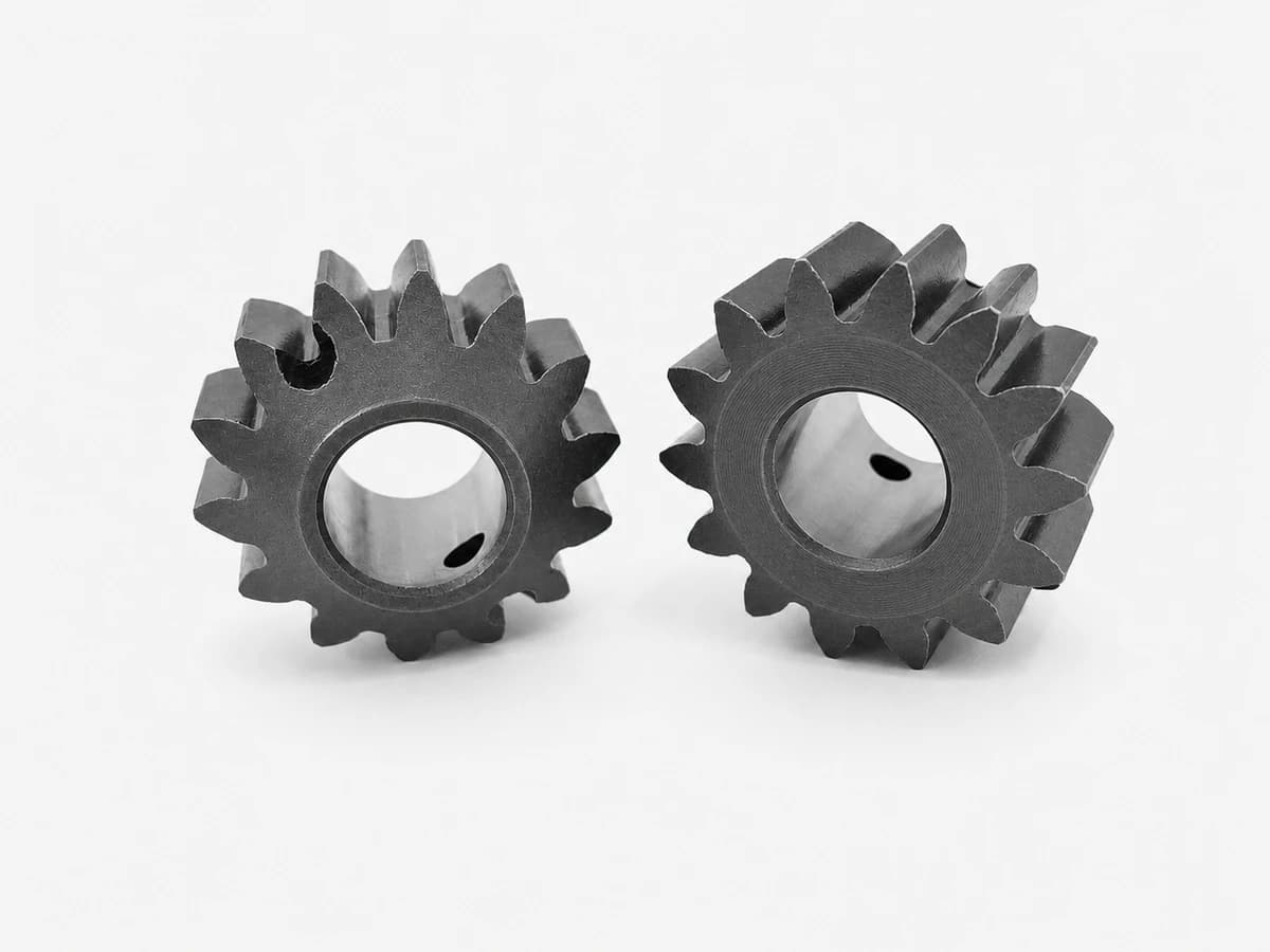
Quick checks before you begin
- Keep every incoming lot identified and separated before opening mixed cartons
- Confirm spur, bevel or L-gear form and the intended installed location
- Count and independently recount every required tooth-count identity
- Measure the bore at defined depths and directions with the agreed equipment
- Record pin-hole quantity, diameter, form and location without forcing a pin
- Quarantine mixed identity, damaged teeth, burrs or results outside the approved evidence
Identify the gear family before measuring it
Cotton picker drive parts that are all called gears can belong to very different interfaces. Manufacturer parts information separates the small picker-bar spur gear, the spindle-shaft L-gear or bevel gear, and the much larger spindle or drum-drive spur gear. Their tooth direction, bore, pin interface, mating component and inspection method are not interchangeable.
The N118289 parts record describes a spindle-bar spur gear and the spindle-components guide identifies a precision cross-hole. A separate AN272800 record identifies a 138-tooth, 12-DP spindle-drive gear and lists KK27793 as its substitute. These records demonstrate why a tooth count must remain linked to one controlled reference; they do not make either specification universal.
| Gear form | Identity evidence to retain | Do not infer |
|---|---|---|
| Small straight-tooth spur gear | Reference, tooth count, bore, cross-hole record and installed picker-bar position | That every small spur gear uses the same bore or pin holes |
| Bevel or L-gear | Reference, tooth direction, bore, roll-pin interface and mating spindle gear | That a similar cone angle or tooth count proves interchange |
| Large spindle or drum-drive spur gear | Current and predecessor reference, tooth count, outside form, bore and mounting interface | That the same diameter or tooth count proves the same pitch and fitment |
Create a separate inspection plan for each reference and gear form. A limit approved for a cylindrical spur gear cannot be transferred automatically to a bevel gear.
Control the lot before inspection begins
Receiving inspection starts with traceability, not a caliper. Keep cartons, labels and parts from different references or production lots physically separated. Assign a receipt or lot ID before cleaning, deburring or moving parts into usable inventory.
Photograph the unopened label, the complete lot and representative parts under even light. If one carton contains mixed forms, references or tooth counts, stop the release and preserve the packing evidence.
- Record purchase order, supplier, reference, quantity, lot or batch label and receipt date.
- State whether the comparison evidence is an approved drawing, first article, retained sample or manufacturer record.
- Confirm the sampling plan and which characteristics require 100-percent verification.
- Use clean trays or dividers so accepted, pending and quarantined parts cannot be mixed.
- Record handling damage, corrosion protection and packaging condition before cleaning.
- Keep any supplier certificate linked to the same lot; a certificate does not replace the physical checks.
Count the teeth without losing the starting point
Tooth count is a strong identity check, but only when it is counted and recorded repeatably. Clean loose debris without altering the flanks. Mark one tooth on a nonworking end face with a removable inspection mark, then count one direction around the gear and return to the mark.
Repeat the count from a different starting position or have a second person recount it. For a large gear, divide the circumference into labeled sectors and total the sector counts. Record the observed count beside the ordered value instead of writing only pass.
- Keep the gear stable on a protected bench; do not roll it across the teeth.
- Use a photograph or sector map to show the marked starting tooth.
- Count complete teeth, not gaps, damaged tips or image shadows.
- If a tooth is chipped, record the physical tooth position and the damage separately.
- Stop and reconcile any difference between the first and second count.
- Do not derive module, diametral pitch, pressure angle, profile or gear quality from tooth count alone.
Two gears can have the same number of teeth and still differ in pitch, pressure angle, tooth thickness, face width, bore, pin interface, accuracy class and mating system.
Measure the bore at defined depths and directions
First inspect the bore for a sleeve, shoulder, taper, keyway, pin intersection, burr, scoring or corrosion. Mark face A and face B so another inspector can repeat the same measurement positions. Let the part and measuring equipment stabilize in the inspection environment before a close comparison.
A caliper can support a preliminary receiving screen when the contact points are visible and the required decision is not close to a limit. Production acceptance should use the bore gauge, plug gauge, coordinate method or other equipment defined by the controlled drawing and inspection plan. Record each observed value; do not hide taper or ovality inside one average.
| Record ID | Measurement position | Evidence to keep | Decision boundary |
|---|---|---|---|
| B1 | Near face A at the first defined direction | Observed value, tool ID and position photo | Do not measure on a chamfer or burr |
| B2 | Near face A at the second direction | Individual result, not only an average | Screens for direction-to-direction difference |
| B3 | Near face B at the first defined direction | Depth and contact method | Screens for face-to-face difference |
| B4 | Near face B at the second direction | Individual result and repeat check | Do not convert a tapered bore into one nominal reading |
| B5 | Middle or shoulder position, when accessible | Defined depth and suitable equipment | Use only when the tool can align repeatably |
| V1 | Bore-entry and internal-condition views | Face A, face B and visible cross-hole | Visual evidence does not replace dimensional acceptance |
Observed sample values support comparison. Nominal dimensions and acceptance limits must come from the approved drawing, master sample or agreed purchase specification.
Record pin holes as an interface, not a cosmetic feature
A pin hole controls assembly and orientation, so its inspection needs more than a front-view photograph. Manufacturer information for the small spindle-bar spur gear describes a precision cross-hole perpendicular to the main bore, while the L-gear records distinguish roll-pin interfaces. That is evidence that hole form and relationship to the bore matter; it is not a universal hole size or fit.
Count the holes and state whether each is through, blind, stepped, intersecting the bore or paired with another hole. Record diameter with the agreed gauge or measuring method, and record location from drawing datums or an approved master. Do not push a production roll pin through an unapproved hole to see whether it fits.
| Pin-hole check | What to record | Quarantine trigger |
|---|---|---|
| Quantity and form | Number of holes; through, blind, stepped or intersecting | Missing, extra or mixed hole form |
| Diameter | Individual result and gauge or tool identification | Result outside the approved limit or a non-repeatable reading |
| Axis and orientation | Relationship to the main bore and defined datum | Visible skew, incorrect orientation or no controlled datum |
| Location | Distance or angle required by the drawing or master | Position outside the agreed evidence |
| Edges and intersection | Burrs, breakout, tearing, cracks and debris | Raised material, crack indication or obstruction |
| Functional verification | Only the agreed gauge, fixture or approved assembly method | Need to force a pin or alter the hole |
Separate visual screening from gear-geometry inspection
A receiving inspector can screen tooth faces for chips, dents, burrs, corrosion, handling marks and mixed tooth form. That visual screen does not establish profile, pitch, helix, runout, tooth thickness or composite error.
ISO inspection guidance treats cylindrical involute gear flanks and bevel gears with separate measurement practices. If the purchase specification controls gear accuracy, the inspection plan must identify the applicable standard, accuracy grade, datum, equipment, master or mating gear, measurement report and acceptance limits.
| Inspection level | Typical evidence | What it can decide |
|---|---|---|
| Identity screen | Reference, gear form, tooth count, photos and ordered interface | Correct family and obvious mix-up |
| Dimensional receiving check | Bore, width, outside form, pin holes and drawing-controlled dimensions | Conformance to the agreed receiving plan |
| Gear-geometry inspection | Pitch, profile, flank, runout or composite results from defined equipment | Conformance to the specified gear tolerance system |
| Functional assembly review | Approved fixture or mating components under the controlled procedure | System-level fit only within the defined application |
The master, fixture, datum, center distance and acceptance rule must match the gear specification. A smooth hand rotation against an unknown gear is not controlled inspection.
Record an inspection result that can be audited
| Field | Required record | Avoid |
|---|---|---|
| Identity | Reference, gear form, lot and installed-system context | Writing only cotton picker gear |
| Tooth count | Ordered value, first count, independent recount and result | Pass with no observed count |
| Bore | B1-B5 values that apply, positions, tool and calibration status | One unexplained average |
| Pin holes | Quantity, form, diameter, orientation, location and edge condition | Looks close to sample |
| Tooth condition | Damage map and representative close photographs | Removing burrs before recording |
| Controlled geometry | Drawing revision, standard, grade and report when required | Assuming tooth count proves pitch or profile |
| Disposition | Accepted, review, quarantine or rejected with authority and date | Moving pending parts into usable stock |
Use clear disposition classes
Acceptance requires the identity and every characteristic defined by the approved inspection plan. A supplier certificate, matching photo or correct tooth count cannot override a failed bore, pin-hole or controlled gear-geometry result.
When limits are missing, classify the lot for engineering or buyer review rather than creating a tolerance at the receiving bench.
| Disposition | When to use it | Next action |
|---|---|---|
| Accepted | Identity and all required results meet controlled evidence | Release the labeled lot and retain the record |
| Engineering or buyer review | The part is traceable but a limit, method or supersession question remains | Hold the lot and obtain written disposition |
| Quarantine | Mixed identity, count mismatch, damage, burrs, pin-hole issue or unverified substitution | Physically separate and open a nonconformance record |
| Rejected | Authorized review confirms nonconformance to the purchase requirement | Control return, rework or scrap under the quality procedure |
The inspector records what was found. The drawing, purchase specification and authorized reviewer control whether that finding is acceptable.
Send a gear inquiry or nonconformance package that controls the risk
- State the gear form, exact ordered reference and installed-system context.
- Attach the carton label, lot ID, full-part views and a marked tooth-count photograph.
- Provide the observed tooth count and independent recount.
- Attach the B1-B5 bore record that applies, including tools and positions.
- Record every pin hole, its form, measured result, orientation and visible condition.
- Separate observed damage from dimensional or gear-geometry nonconformance.
- Identify the drawing, approved sample, standard and acceptance revision used.
- State quantity affected, quantity inspected, requested disposition and required response date.
The supplier should be able to identify the exact lot, repeat each inspection point and answer the open fitment or conformance question without guessing from a marketplace photo.
Technical basis for this article
The article paraphrases and organizes the sources below. It does not copy a service manual, and it does not replace the current documentation for the exact machine.
- John Deere Cotton Picker Parts: Spindle ComponentsJohn Deere Parts | technical guideOpen source
- N118289 Spindle Bar Spur GearJohn Deere Parts | technical guideOpen source
- AN272800 138T, 12DP Spindle Drive Spur GearJohn Deere Parts | technical guideOpen source
- ISO/TR 10064-1:2019: Measurement of cylindrical gear tooth flanksInternational Organization for Standardization | technical guideOpen source
- ISO/TR 10064-6:2009: Bevel gear measurement methodsInternational Organization for Standardization | technical guideOpen source
- Quick Guide to Precision Measuring InstrumentsMitutoyo America Corporation | technical guideOpen source
- Rule Model for Selecting Dimensional Measurement Equipment in Inspection PlanningNational Institute of Standards and Technology | technical guideOpen source
- Cotton picker parts inquiry data standardYUCHENG HARVEST | internal standardOpen workflow
Questions buyers and technicians ask
Is the same tooth count enough to confirm a spindle drive gear?
No. Also confirm gear form, pitch or module system, pressure angle when controlled, tooth width, bore, pin interface, accuracy requirement, mating components, reference and installed location.
How should a large gear tooth count be checked?
Mark a starting tooth, divide the circumference into labeled sectors, total the sector counts and perform an independent recount. Keep the marked photograph and both observed totals.
Can a caliper approve the bore?
It may support a preliminary screen when the decision is not close to a limit. Production acceptance should use the equipment, contact method, calibration status and limits defined by the inspection plan.
Can I test a pin hole by forcing in the roll pin?
No. Use the agreed gauge or controlled assembly procedure. Forcing a pin can alter the hole, damage the part and hide the original condition.
Does a clean tooth surface prove the gear is correctly manufactured?
No. Visual condition cannot establish pitch, profile, flank, runout, heat treatment or accuracy class. Those characteristics need controlled inspection evidence when required.
Should every incoming gear receive a full gear-measuring report?
Not automatically. The buyer's risk, drawing and quality plan should define which identity checks, dimensions, sampling and gear-geometry reports are required for each reference and lot.