Quick checks before you begin
- Stop, isolate and prevent restart. Wait for all motion to stop; secure raised units with the specified mechanical supports.
- Record the unit, serial number, row and installed position before removing components.
- Keep parts, shims and observations separated by assembly. Use qualified personnel and the complete applicable service procedure.
Identify the assembly before interpreting slipping
TM2109 covers an idler-gear slip-clutch arrangement in Section 60 and a gearcase output-shaft clutch arrangement in Section 100. Similar names do not make their components, lubricant instructions or adjustment criteria interchangeable.
Record where the clutch is installed, what happened before the complaint and which components were previously replaced. Slipping is a reason for inspection, not permission to tighten the spring until the symptom disappears.
- Inspect the drum-drive path
Separate drum, shaft, bearing and gear findings before ordering.
- Check gearcase oil, leaks and identity
Identify the lubrication type and installed box before choosing service parts.
Check the mating surfaces as a set
Keep the jaws and idler gears together in their original locations during an authorized repair. Separate assemblies in labeled trays; do not mix similar-looking used components to produce a set.
| Component | Finding to record | Why it matters |
|---|---|---|
| Clutch jaws | Wear and glazed contact faces | The manual specifies paired replacement in this idler repair context |
| Jaw pin pockets | Wear at the pockets in the idler gear | New jaws do not correct worn mating pockets |
| Idler gear teeth | Chipped or worn teeth and their locations | The gear needs its own condition assessment |
| Internal bronze bushing | Wear or damage | Bushing condition is distinct from tooth condition |
| Upper/lower bearings | Wear or damage, with position retained | Different positions must remain identifiable |
| Spring | Damage and identity | Free length alone does not establish correct clutch behavior |
Do not substitute a guessed dimension or spring setting
The reviewed manual contains different idler bushing and sleeve dimensions in its specification table and repair text. This page deliberately does not choose one as a universal wear limit. Record what was measured and resolve the applicable structure and revision before acceptance.
Gearcase slip-clutch checking includes a defined test arrangement and multiple readings. That procedure is not an instruction to use a single torque reading or a guessed washer count on an unidentified clutch.
Spring-loaded assemblies and retained internal parts require controlled handling and the prescribed tools. Do not dismantle, preload or test the clutch using this abbreviated checklist.
A paired repair does not define the sales package
The idler repair text identifies N190954 in its paired-jaw replacement instruction. The current John Deere product record calls N190954 a right-side housing drum slip clutch. Confirm the actual position and required quantity; do not interpret the reference as a complete clutch assembly or a universal left/right part.
YUCHENG HARVEST can review the reference, removed-part photographs and required quantity. Ask which components are included rather than assuming a gear, bearings, spring and hardware arrive together.
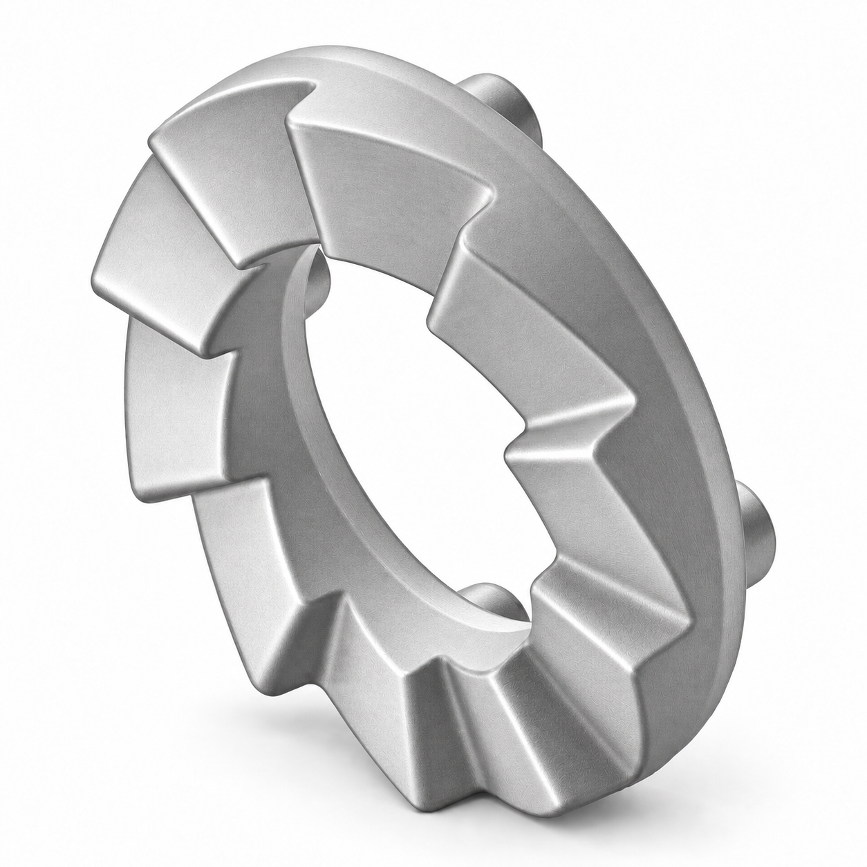
N190954: one component, not the complete clutch
 View full-size image · Back to return ←
- Record the actual contact-face condition and the mating pin pockets separately.
- Keep the installed position, removed reference and required quantity together.
- The gear, spring, bearings and hardware are not shown. Confirm supply contents rather than assuming they are included.
Reference illustration, not a photograph of wear. The registered Deere identity is right-side housing drum slip clutch. The manual's paired-jaw repair instruction does not make this image a complete clutch, a matched sales pair or a universal left/right replacement.
Approved N190954 image register, reviewed 14 September 2026; TM2109 (20 July 2020), 60-05-5, paired-jaw context.Compare the parts category →- Look up N190954
Right-side reference identity; confirm installed position and supply contents before ordering.
- Identify gears and drive parts
Compare the installed reference, location and interfaces before requesting replacements.
Close the repair with the original complaint still visible
- Retain the installed location, jaw and mating-pocket observations and the gear/bearing assessment.
- Keep unresolved measurements open rather than marking the assembly serviceable from a photograph.
- Have qualified service complete retention, lubrication and prescribed checks before return to service.
- Compare the completed repair with the original complaint under the approved verification procedure; do not continue running with unexplained damage.
Keep the four clutch locations separate in the enquiry
Do not transfer a spring, torque, washer count or sensor relationship between these assemblies. The same generic supplier label can refer to different service items.
For gearcase work, record left/right and inner/outer or through/offset position using the applicable viewing convention, together with oil-type or grease-type identity. Keep backlash, bearing end play and clutch test results as different measurements. Unresolved dimensional conflicts remain pending rather than being converted into a parts acceptance limit.
| Clutch context | Reference information needed |
|---|---|
| Section 60 idler assembly | Idler/shaft location, jaw and pocket findings, gear and bearing identities. |
| Section 100 gearcase output | Box type and position, drive interface and the workshop’s test context. |
| Section 120 VRS knife | Actual VRS configuration, knife-drive location and sensor arrangement. |
| Section 120 VRS front feeder | Feeder position, clutch/bearing identities and sensor arrangement. |
- VRS clutch and sensor identification
Knife and front-feeder arrangements require their own records.
- Identify the gearcase
Record box position, lubrication type and interface before ordering.
Technical basis for this article
The article paraphrases and organizes the sources below. It does not copy a service manual, and it does not replace the current documentation for the exact machine.
- TM2109 — PRO-12, PRO-12 VRS and PRO-16 Picking Unit Repair (20 July 2020), Sections 50, 60 and 100John Deere Des Moines Works | repair manual
Reviewed printed pages 50-05-1–19, 60-05-1–8 and 100-05-1–24, including illustrations. Bibliographic reference only. Configuration-specific service information remains controlling.
- N190954 — Housing Drum Slip Clutch, Right SideJohn Deere Parts | technical guide
Reference identity only; the manufacturer requires equipment-specific fit confirmation.
Open source - TM2109 (20 July 2020), Sections 60, 100 and 120; component-identification comparisonJohn Deere Des Moines Works | repair manual
Source-bounded identification and inspection summary. The purchased manual is not hosted here; follow the applicable current service procedure.
Questions buyers and technicians ask
Can new jaws fix worn pin pockets?
New jaws do not establish that the mating pockets are serviceable. Inspect both and have the workshop decide the required repair.
Is N190954 a complete slip-clutch assembly?
Do not assume so. Confirm the reference identity, quantity and included components. The paired-replacement instruction is not a packing list.
Can I tighten the spring to stop slipping?
Not as a substitute for identifying the assembly and investigating the complaint. Use the full applicable inspection and setting procedure with qualified personnel.