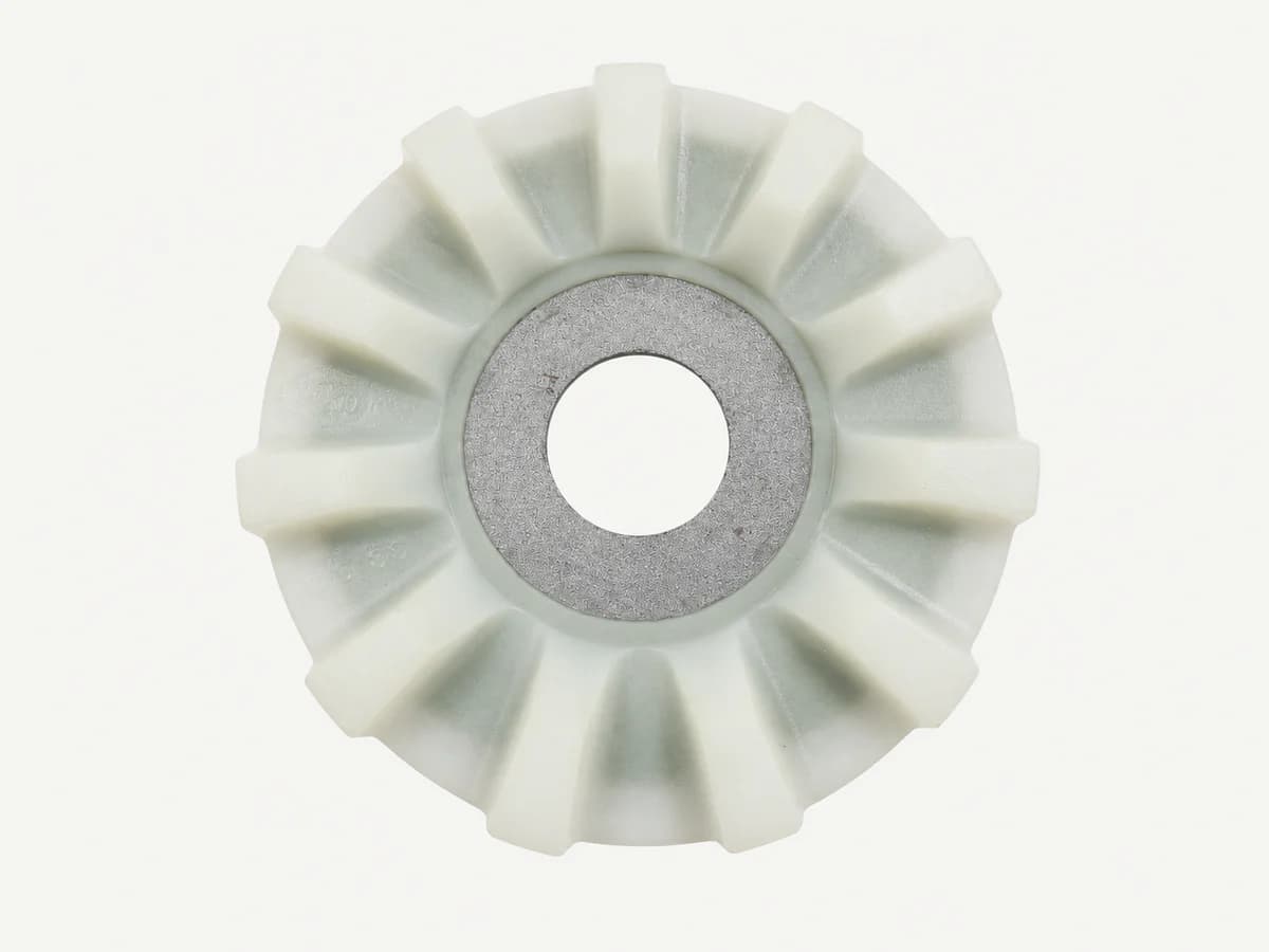
Quick checks before you begin
- Label the loose doffer and mark face A and face B
- Record whether the bore contacts metal, polymer or another insert surface
- Measure the inside diameter at defined positions in more than one direction
- Keep the original readings instead of reporting only an average
- Send the shaft, assembly or installed-position evidence with the inquiry
Treat small bore and large bore as ordering labels
YUCHENG HARVEST currently offers one standard doffer product in small-bore and large-bore versions. Those names separate the two available factory options; they are not universal industry dimensions and should never replace a measured inside diameter.
Official parts literature also separates doffers by shaft-system context, including solid-shaft and hollow-core applications. That distinction shows why a bore decision must remain connected to the installed shaft, assembly and controlled reference rather than appearance alone.
Write the measured bore, sample ID and shaft context on the quotation. A supplier's small-bore label may not equal another supplier's label.
Identify the supply form and bore construction first
- State whether the sample is one loose doffer disc or part of a complete doffer column or assembly.
- Record every visible part number, package label and known machine or row-unit context.
- Mark the two flat faces as face A and face B so later readings can be repeated.
- Photograph the bore straight-on from both faces under even light.
- Record whether the working bore surface appears to be molded polymer, a metal sleeve or insert, or another construction.
- Note shoulders, chamfers, steps, slots, notches, damage or material pushed into the bore without guessing their function.
- Keep the mating shaft or a labeled shaft measurement record with the doffer sample when possible.
Prepare a reliable inside measurement
Measure a loose, safely removed doffer on a stable bench. Clean loose debris from the bore without cutting, sanding, pressing or reshaping the polymer or insert. Let the part and instrument stabilize in the same inspection environment before a controlled comparison.
For a quick RFQ screen, suitable caliper inside jaws can provide a useful observed value when the contact points are visible and the bore is accessible. For production approval or close acceptance limits, use the measuring equipment and calibration method agreed in the inspection plan.
- Check the measuring tool's condition and zero before use.
- Record tool type, identification, resolution and calibration status.
- Use light, repeatable contact so a flexible bore is not compressed into a smaller reading.
- Keep the contacts at the same axial depth and align them across the bore rather than across a short chord.
- Repeat at another angular direction and, when accessible, at both faces or a defined middle depth.
- Stop and document the condition if damage, an irregular insert or heavy wear prevents repeatable contact.
Metrology guidance treats equipment selection, contact geometry and measurement uncertainty as part of the plan. Extra display digits do not correct poor centering or a flexible, damaged bore.
Build a bore record that another person can repeat
Give every reading an ID and show the contact location on a marked photo or sketch. Record the observed values individually. A minimum and maximum observed result is more useful than an average that hides ovality, taper or inconsistent contact.
The fields below are an identification and purchasing template. They do not publish a nominal doffer dimension or manufacturing tolerance.
| ID | Record | Defined position | Ordering purpose |
|---|---|---|---|
| B1 | Inside diameter, face A | Defined depth near face A; readings across two marked directions | Primary bore-option evidence |
| B2 | Inside diameter, face B | Defined depth near face B; repeat the marked directions | Shows face-to-face difference |
| B3 | Inside diameter, middle | Only when the selected tool can reach and align repeatably | Screens for an internal step or taper |
| B4 | Working bore length | Axial length of the surface that contacts the shaft or insert, with endpoints shown | Separates bores with similar entry size but different engagement |
| D1 | Doffer outside diameter | Maximum outside diameter with the orientation recorded | Secondary sample comparison |
| T1 | Overall disc thickness | Between defined flat faces without compressing the lugs | Secondary sample comparison |
| I1 | Insert or sleeve outside diameter | Only when a distinct insert is present and accessible | Documents bore construction |
| V1 | Bore and lug photographs | Both faces, side profile, bore close-up and sample label | Preserves visual identity and condition |
Use the readings to classify the sample, not to guess fitment
| Observed evidence | Buyer action | Do not conclude |
|---|---|---|
| Readings repeat and match the approved small-bore record | Quote the small-bore option and attach the record | That every machine using a similar shaft is compatible |
| Readings repeat and match the approved large-bore record | Quote the large-bore option and attach the record | That large bore is a universal size |
| Face A and face B differ | Check for a step, taper, wear, insert movement or measurement error | That one reading can represent the complete bore |
| Angular readings differ | Retain the individual values and inspect for ovality, damage or poor alignment | That the average is the true acceptance result |
| No controlled option record exists | Send the retained sample and shaft context for supplier confirmation | That a visual comparison is sufficient |
Also confirm shaft form, engagement length, insert construction, outside diameter, thickness, lug geometry, assembly position and the controlled product reference.
Control wear and deformation in a used sample
A used doffer can help identify an order, but the bore may show wear, embedded debris, heat effects, insert movement or permanent deformation. Mark those conditions and keep the readings as observed sample data, not as a new-part specification.
When possible, compare the used sample with a confirmed new doffer from the same controlled reference. Cotton harvester guidance also treats the doffer as part of a close-tolerance working system, so a worn component should not be used to create installation or adjustment values.
- Do not sand or ream a used bore before measuring it.
- Do not press a distorted doffer flat to obtain a preferred reading.
- Photograph cracks, displaced inserts, polished contact bands and uneven wear.
- Keep used and confirmed-new samples in separate labeled bags or trays.
- Escalate unusual contact, heat or shaft damage to the qualified service review.
Repeat the bore check when the order arrives
- Confirm the carton and batch labels before mixing parts from different lots.
- Keep small-bore and large-bore batches physically separated.
- Inspect bore construction and visible condition against the approved sample.
- Repeat B1-B4 with the same method defined during sample approval.
- Record the individual results required by the agreed inspection plan.
- Quarantine mixed labels, non-repeatable bores, damaged inserts or results outside the agreed acceptance evidence.
- Retain one labeled sample from the accepted batch when the buyer's quality plan requires it.
Send a doffer inquiry that cannot be misread
- State individual standard doffer disc, not a complete column or assembly.
- Select small bore or large bore only after comparing the measured record with the approved option.
- Attach B1-B4, D1, T1 and the face-A/face-B photographs that apply.
- Provide the machine, row-unit, shaft and removed-position context without claiming universal fitment.
- State whether the sample is used, confirmed new or of unknown history.
- Request trial quantity, annual estimate, packaging separation and required quality documents.
- Agree the first-sample and incoming-inspection method before volume production.
The supplier should be able to repeat the bore measurement, identify the selected option and list every remaining fitment question before quoting.
Technical basis for this article
The article paraphrases and organizes the sources below. It does not copy a service manual, and it does not replace the current documentation for the exact machine.
- John Deere Parts Catalog: Cotton Parts and AttachmentsJohn Deere | technical guideOpen source
- Preseason Procedures for Spindle-Type Cotton HarvestersCotton Incorporated | technical guideOpen source
- Quick Guide to Precision Measuring InstrumentsMitutoyo America Corporation | technical guideOpen source
- Rule Model for Selecting Dimensional Measurement Equipment in Inspection PlanningNational Institute of Standards and Technology | technical guideOpen source
- Cotton picker parts inquiry data standardYUCHENG HARVEST | internal standardOpen workflow
Questions buyers and technicians ask
Can I identify doffer bore size from one front photo?
No. A front photo can show general construction, but it cannot establish a repeatable inside diameter, axial step, insert condition, shaft interface or machine fitment.
Are small-bore and large-bore doffers standard sizes worldwide?
No universal dimensions should be assumed from those names. They are ordering labels that must be tied to the supplier's controlled specification, measured sample and shaft context.
Is a caliper enough to measure a doffer bore?
It can support a preliminary RFQ when the bore is accessible and the method is recorded. Production acceptance should use the agreed instrument, calibration status, contact method and limits.
Why do bore readings change around the same doffer?
Possible contributors include poor centering, different measurement depth, flexible material, debris, wear, ovality, taper or insert movement. Preserve the readings and inspect the cause instead of averaging them away.
Does matching the bore diameter prove the doffer will fit?
No. Confirm the shaft and assembly interface, engagement length, bore construction, outside diameter, thickness, lug geometry, reference and machine context.
Can a worn doffer be used as the production master?
It can support identification, but wear or deformation may have changed the bore. Use a confirmed new sample, controlled drawing or agreed acceptance plan for production approval.